Air sampling installations should be given the following considerations and as a minimum consist of the following:
- Siting of equipment, including the detector, control equipment, power supplies, repeat or remote displays and any other device associated with the ASD system
- Electrical installation to include power, loop and associated interface wiring
- Mechanical installation to include installation of pipe, necessary mounting/fixing assemblies and any other associated works
- Inspection, testing, commissioning including performance tests of the installed systems
Siting of Equipment
Wherever possible, equipment should be installed at a location that is easily accessible and gives consideration for future maintenance & servicing. In particular, ensure that sufficient space is provided to all points of access such as covers, connectors and cable entries.
For the detectors the maintenance requirements for any filters and removal of sampling pipes should be considered.
Whenever the detector is installed outside the risk, consideration should be given to arranging for an air return of the exhaust air back into the protected area to avoid the effects of any significant pressure difference. Generally differences of less than 50Pa do not require return of the exhaust but this must be confirmed by the ASD manufacturer.
Where the detector has indicators or a display that is required to be visible it should be sited accordingly.
Local environmental conditions and risks should be taken into account. For example, avoidance of inadvertent mechanical damage, moisture, extreme temperature etc.
Electrical Installation
Generally ASD electrical cabling should be to National Standards, in the UK it should comply with BS 5839 Part 1:2008 clause 26. A risk assessment should determine whether enhanced or standard cabling is needed:
- From a local power supply to the ASD.
- From the ASD to the house fire system/CIE.
- To any remote or repeat ASD displays.
Cables
- Power cable should be 2.0mm2-2C of sufficient current carrying capacity.
- Control cable should be 0.75mm2 strands cable.
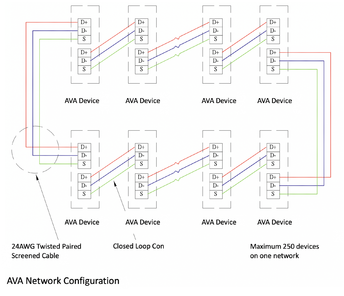
- RS485 network should be 24AWG twisted pair shielded cable.
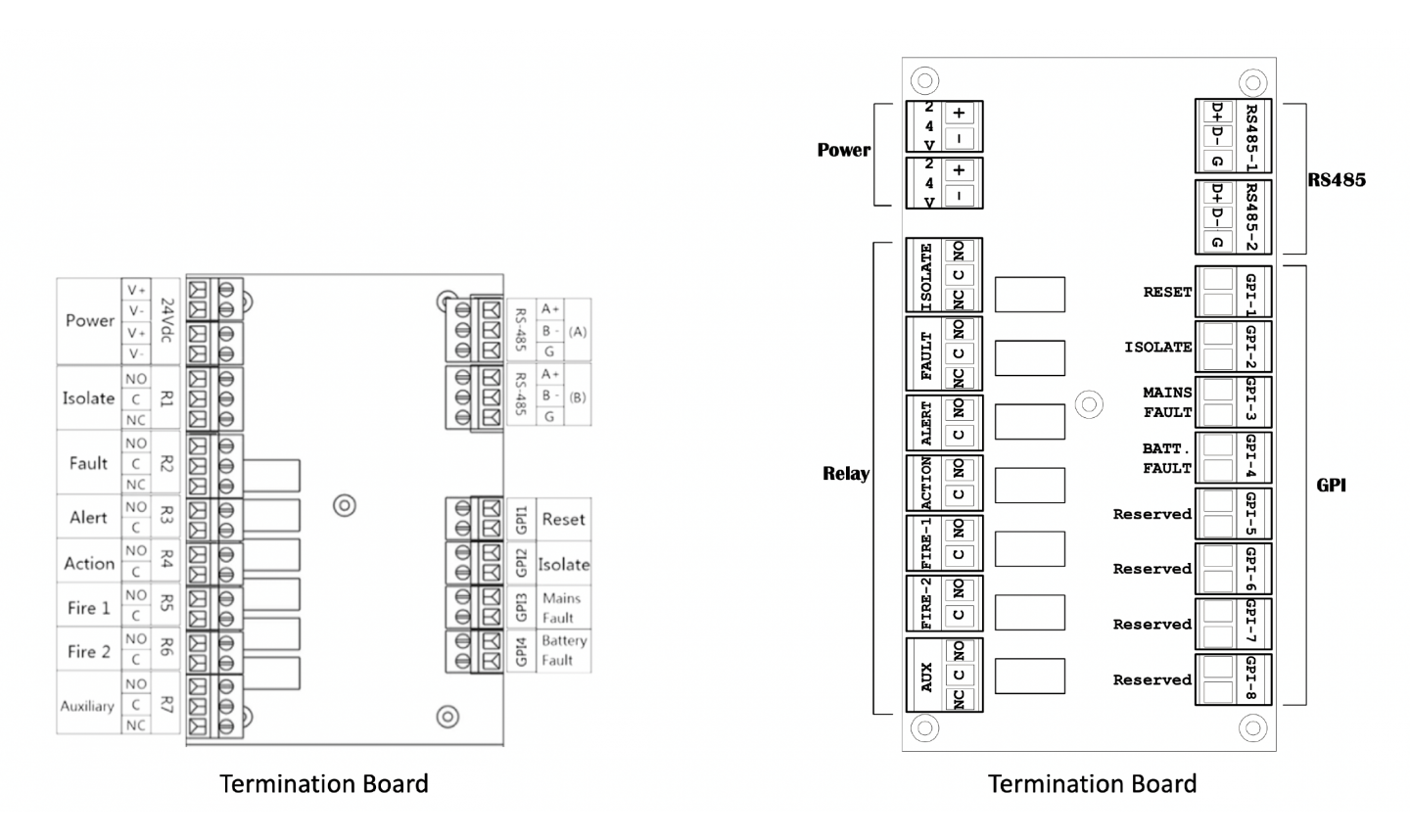
Power Supply Connections
Two 24Vdc power terminals on the termination board. One must be connected to a 24±20% (19.6~28.8) DC Power Supply. The device may be powered by any EN54-4 compliant monitored 24DC power supply of sufficient capacity.
Relay Connections
There are 7 configurable relays on the termination board.
- Isolated (NO/NC)
- Fault (NO/NC)
- Alert (NO)
- Action (NO)
- Fire-1 (NO)
- Fire-2 (NO)
- Aux (NO)
Note: NO=Normally Open NC=Normally Closed Com=Common
The relay rating is 2A@30Vdc. If load connected is more than the relay rating, a transfer relay suitable for the rating should be used.
Every relay has its indicator (LED) on board to indicate its on/off status. It’s easy for the user to know the relay status and to trouble shoot if the connected device doesn’t go out properly.
All relays are configurable to one of the following functions: Alert, Action, Fire 1, Fire 2, Fault, Isolate, and Auxiliary. The relay output function printed on the termination board is the factory default setting. Users can change the relay function using LCD programmer on the front panel or the AVAnet Management computer Software to change the setting. However, the second relay, which circuit is designed to normally closed to give a trouble signal when the device is powered off. Care should be taken for the relay’s NO or NC connection when changing relay functions.
GPI, General Purpose Input
There are eight General Purpose Input terminals on FANFARE termination board. Those inputs are designed to monitor the status of the connected devices. The connected devices monitored by the GPI can be just a button, a fault relay from the power supply, or even alarm relay from other detector. Short circuit the pair of the input pins makes AVA to activate associated function defined in the GPI settings. There are 16 possible functions falls in the following categories:
- Device Control: Reset, Isolate, Silence, Test, Scan,
The GPI terminal can be connected to a remote button, a control/output module of the fire alarm system, or a PLC so those control function can be performed remotely, or by other systems.
- Power Fault Monitoring: Mains Fault, Battery Fault, Power Fault
It is sometimes required by local code that the fault status of the mains and/or battery condition of the detector’s power supply should be monitored. In this case, the AVA detection device will signal a fault when the connected relay of power supply is activated. The AVA fault condition can then be monitored by a fire alarm system when its fault relay is connected the fire alarm system input module.
- Sensitivity Change: Sensitivity Mode 1, Sensitivity Mode 2
In some applications, the detection area environment background smoke level is different in a day. For example, in a work hours the background smoke level is usually higher than the non-working hours. Sometimes, outside pollutants go into the detection area can generate false alarm. There are needs to decrease the sensitivity to prevent the false alarm or increase the sensitivity to provide better protection in a daily basis or in certain situations. In this case, the GPI can be connected to a button, a timer, a PLC or even a relay output of other AVA detector sensing the pollutant level from outside, so that that sensitivity adjustment can be made manually or locally.
- User Defined Device Monitoring: UDI-1, UDI-2, UDI-3, UDI-4, UDI-5
The UDI, User Defined Input is usually used to monitor the status (relay) of other detection device, like gas sensors, temperature sensors, or other aspirating smoke detectors.
RS-485
- Two RS-485 Terminals
- Built in RS-485 repeater, the cable length can be extended to next device for another 1.2km.
- RS-485 Network can be configured in closed loop for better communication reliability. The communication can switch direction to communicate with devices behind the failure point when there’s device failure, line break or line short circuit.
- AVAnet Management System (a computer software) can monitor all devices on network.
- SCADA/HMI/PLC systems capable of Modbus RTU open protocol can communicate with AVA devices.
Mechanical Installation
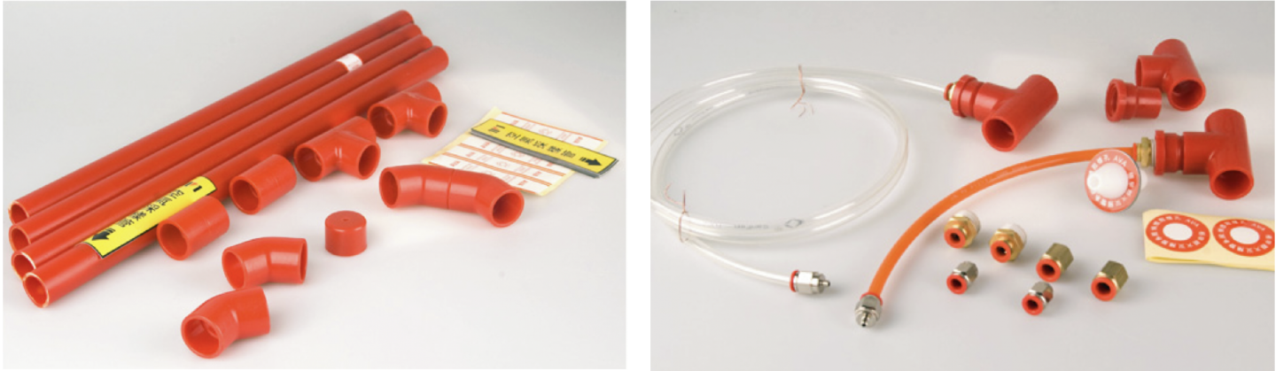
Installation of the pipe-work in PVC, ABS or any other material recommended by the manufacturer should give consideration to the following external influences:
- Undue stress
- Mechanical Impact
- UV radiation
- Temperature extremes
- Future building operations
All pipes should be clearly labelled to indicate its purpose in a fire protection system.
Installations in red ABS pipe are considered normal but alternatives are permitted as some applications require pipe to be installed to match the building aesthetics.
Suitable and sufficient fixing supports must be used and designed to each individual application. They should be agreed with all appropriate parties concerned before installation commences. Guidance should be taken from the ASD manufacturer and/or pipe manufacturer.
Typical fixings include:
- Open or closed clips for surface mounting
- Fast fix clips and tie wraps onto suitable beams, joists or other structural steelwork
-
Double tie wrap onto false floor stanchion
Installations of pipe work in extreme environments should give special consideration to thermal expansion and contraction when supporting and jointing pipe. Guidance should also be sought from the ASD manufacturer and/or the pipe manufacturer.
Metal pipe installations should be earthed in accordance with national Standards.
Consideration should be given to the fire compartmentalization of the building fabric. While the penetrations required for an aspirating sampling pipe are typically deemed to be small (see
BS 9999:2008 clause 33.4.17) and so do not require special measures (e.g. intumescent seals), fire stopping should be used around the pipe to keep the penetration as small as possible. However, where there are multiple pipe penetrations, it is good practice to use intumescent seals in addition to the provisions recommended in BS 9999:2008.
Sampling points
Sampling points can either be drilled directly into the main sampling pipe or be positioned
several meters from the main sampling tube using extended sampling pipe or capillary tubes.
Extended sampling pipe or capillary tube
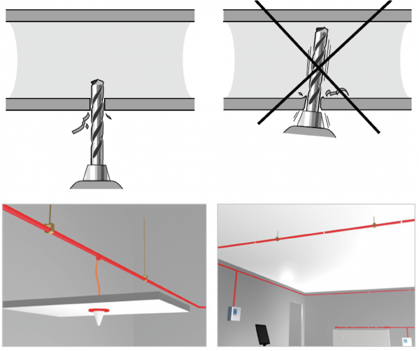
If a concealed pipe installation is required, capillary air sampling can provide a solution. In many cases the main sampling pipe is installed in the ceiling void/building structure and a capillary tube taken from the main pipe to the sampling point. The sampling points are then at the end of this capillary tube.
The sampling point may be flush mounted or protrude into the space to be protected (see figure 4). In some cases it is appropriate to have a concealed sampling point.
Note: The flush mounted Capillary is often used for thicker ceilings as they are fixed from the front.
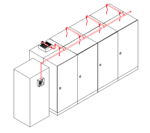
Capillary sampling may be used to position sampling points in specific locations - e.g. in the outlet flow from enclosed equipment or near specific hot spots on a machine, thereby negating the need to run the main sampling pipe through complicated routes
Particular attention should be paid to the mechanical integrity and routing of the capillary tubes and fittings to minimise the risk of inadvertent disconnection or damage.
The maximum capillary length should be established by the system manufacturer.
Sampling points
These may be realized either by drilling custom sizes or drilling common sizes and using reducing ports or sheets. In either case care should be taken to make sure the sampling point has the correct hole-size and that any swarf from the drilling process is removed from the sampling pipe.
Ensure that it is clear which party is responsible for drilling the sampling holes. Every sampling point should be clearly labelled.
The following parts of an ASD should be clearly labelled;
- Sampling Pipe
- Sampling Points
- ASD Units
-
Power Supplies and battery enclosures (if separate)
The labelling should clearly identify the purpose and where appropriate the zone/location of the equipment.Where discreet installations are required labelling will be detrimental to the desired visual effect. In this situation it is essential to supplement the ASD with a plan of the protected area showing sampling points and/or sampling pipe locations